• This web page was last updated on Sun, 02 Nov 08 at 2005 hours
  • Questions about this page? Contact us by email.

Building and Using Sanguino Devices - Part I    Part II
Bob Cochran - September 2008

This web page documents my work with the Sanguino computing devices. I became interested in them originally by looking at Brian Riley's Wulfden which has a page showing the Sanguino and offering kits for sale. I looked more carefully at the photos he offered, and recalled my experiences with building the Bare Bones Board. Then I looked over the kit assembly instructions at sanguino.cc. I also looked at the NYC Resistor website a little bit to see how that connects to the Sanguino. I couldn't see anything obvious. For example, there were no classes devoted to constructing and using the Sanguino. But I like the idea of working with the Freeduino platform, and the Sanguino seemed an interesting device to use. So I went ahead and ordered a kit.

Building the Sanguino

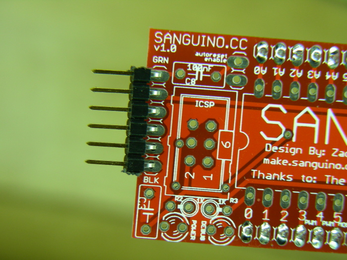
I had a generally good building experience. Installing the header pins (seen from the bottom in this view) was a bit of a challenge. The advice I read was to align each each header row for the PCB by inserting them into a breadboard. Then put the PCB on top of the headers. Then solder one pin on each end of the headers. This may or may not make sure the header pins are straight in the vertical plane. The Sanguino PCB itself may not be perfectly flat. If it is slightly elevated from flat then headers won't be soldered flush to the PCB surface. I dealt with this by pressing down on both ends of the PCB with my left hand while I tacked the pin on one end of a header with a small solder blob hanging off the soldering iron tip. I melted more solder on the iron tip, pressed down on the PCB with my left hand, and got the pin on the other end of the same header row. I repeated this two more times for the next header row.

  • It can be very hard to pry the headers out of the breadboard. I used a small Phillips screwdriver to help me with this. A strong thin plastic rod of some sort might be a better prying device.
  • Notice that one row of headers has two more pins than the other row.
  • The PCB is pretty wide. I wonder if bringing pins out to screw terminals might be an option for a future board revision.
  • Time will tell if the PCB can survive being pried off of a breadboard with various tools.

A closeup view of the serial programming header. Do you see the text at each end of the header marked "grn" and "blk"? That tells you which wire colors should be on each end when you plug in the FTDI programming cable.

Before installing the ATMega 644P chip, I plugged in a 12v, 800 mA wall wart to the power connector and checked that the green LED came on. It did. I also checked Atmega pin 10 for 5v. I measured 4.99v which is fine. I plugged in the FTDI programming cable and checked that the green LED also came on for that. It did. Then I installed the 644P chip. I had not previously put any sketches on the chip or otherwise used it in any way. When this is properly done (with pin 1 of the chip oriented correctly on the socket), and power is applied immediately after, the red LED will start blinking. It is connected to digital 0. I believe this applies to kits purchases from Brian Riley at Wulfden.org.

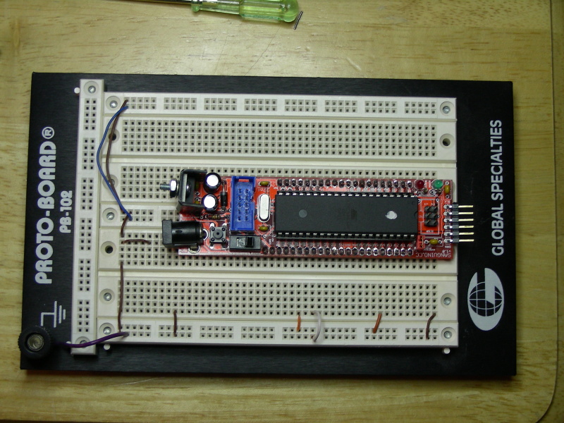
I looked around my workbench for a sufficiently large breadboard for the Sanguino. My 3M brand breadboard, a really good one with a triplet of boards on it, has power rails which are just a little too wide for the board. So I next turned to my Global Specialties PB-102 Proto-board, and after clearing out the circuit that had been resident on that, the Sanguino just about fit. The wire connections shown in the photo make no sense and are not used. I rearranged them into a real circuit when I actually put my first sketch on it.

The Proto-Board costs more to buy than the Sanguino kit itself. Cheaper dual breadboards will still likely exceed the cost of the Sanguino, and a larger breadboard is bulky.

  • I wonder why the Sanguino doesn't have a hole on each PCB corner for mounting to project enclosures.
  • A new Sanguino board version which brings Atmega 644P pins out to screw terminals looks like a great idea. Or use female headers instead of pin headers.

Sanguino 1.1 Software Setup and Initial Device Testing

Let me start this section by reminding the reader that I am an electronics beginner. I have very little expertise. Don't consider my work here to be what an electrical engineer would do. Did I build the Sanguino kit sufficiently well that it actually works? To test this, I turned my attention to setting up the Arduino software IDE so it can upload to the Sanguino. I downloaded the Sanguino 1.1 software being offered on Sanguino.cc. I originally wanted to do this on Fedora 8 Linux. After logging on to Fedora, I edited my existing Arduino-0011 software adding the various items from Sanguino-1.1 according to directions. (Arduino-0012 for Linux has not been released as of this writing.) The Linux version of Arduino launches correctly after updating it with Sanguino 1.1 software and does indeed show the Sanguino in its list of boards. But I wanted to bring the Sanguino to my office and demonstrate it to some associates. This meant taking my wife's laptop to the office, and that machine runs Windows XP (Service Pack 3). I logged onto it and downloaded Arduino-0012 for Microsoft Windows and modified it with Sanguino-1.1 software, again following the appropriate directions. Arduino-0012 for Windows launched without a problem after these modifications. Then, still using this Microsoft Windows version of Arduino, I looked in its' "examples" directory and decided to modify the "Blink" sketch that I found there so that an LED on Digital 22 would be blinked. I made a quick change to the sketch, then uploaded this to the Sanguino board. Instant gratification! The LED began blinking. Then I modified the code again to add a blinking effect for the LED on digital 23. I'm a big fan of incremental coding changes and testing. This sketch compiled properly but would not upload to the board. I kept getting various synchronization and/or timeout errors each time I clicked the Upload icon. Finally, I clicked the Upload icon, and then immediately pushed the reset button on the Sanguino and that got the sketch uploaded. Success! This too worked, and I now had both LEDs blinking. The Arduino IDE seems very fussy about managing sketch uploads. And perhaps the Sanguino is fussy, too? But here my inexperience shows up.

Update: Sanguino creator Zach Smith suggested I look at the auto-reset jumper. He added a note to the assembly/build instructions on sangino.cc to emphasize that you must install the auto-reset jumper or you will have to press the reset button each time you upload a sketch. Although on my board the jumper was indeed on the pins, theoretically enabling the auto-reset feature, it didn't seem to be working for me. I pried the Sangiono off the breadboard and inspected my soldering work on those pins. It seemed fine. I also looked at the preferences.txt file used by the Arduino-0012 software, but saw nothing obviously related to auto-reset functionality. By the way, this board feels like it will take a "Gorilla" bar to get it off a breadboard. I hope I won't have to do this too much more. Since the soldering was okay, I plugged it back in and replaced the pink jumper with a white one, mainly to make it show up better in future photos. The new jumper seems to have helped to get auto-reset working! So if you have trouble with auto-reset, consider replacing the jumper with a different one. But also read below for more details that could influence this.

A nice feature of the Arduino-0012 IDE is that it will offer you a "help" type URL specific to the general issue you are experiencing, such as uploads that are failing. In my case I was pointed to the troubleshooting guide.

So, at this point, I know I can successfully upload a sketch to the Sanguino (with some fussing), and digital 22 and 23 work as expected. Considering the device has 40 pins this is not a thorough test, but it is a very good sign of great things to come.

So, at this point, I know I can successfully upload a sketch to the Sanguino (with some fussing), and digital 22 and 23 work as expected. Considering the device has 40 pins this is not a thorough test, but it is a very good sign of great things to come.


/*
 * Blink_Sanguino
 *
 * The basic Arduino example. Turns on an LED for one second,
 * then off for one second, and so on... 
 *
 * http://www.arduino.cc/en/Tutorial/Blink
 *
 * Modified by Bob Cochran for the Sanguino board.
 * It causes two different LEDs, connected to 
 * digital 22 and 23 respectively, to blink.
 * 
 * You may copy and use this code for any purpose.
 *
 */

int ledPin = 22;                // LED connected to digital pin 22
int ledPin2 = 23;               // LED connectedto digital pin 23

void setup()                    // run once, when the sketch starts
{
  pinMode(ledPin, OUTPUT);      // sets the digital pins as outputs
  pinMode(ledPin2, OUTPUT);     //
}

void loop()                     // run over and over again
{
  digitalWrite(ledPin, HIGH);   // sets the LED on
  delay(1000);                  // waits for a second
  digitalWrite(ledPin, LOW);    // sets the LED off
  delay(1000);                  // waits for a second
  digitalWrite(ledPin2, HIGH);  // turns on the red LED
  delay(1000);                  // wait 1 sec
  digitalWrite(ledPin2, LOW);   // turns off the LED
  delay(1000);                  // wait another 1 sec
}


Saved By The P4

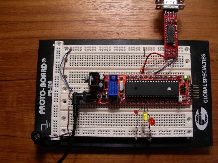
After coming home from my workplace this past Friday night (September 26), an awful realization struck me: I had forgotten to bring the FTDI programming cable home with me. And it was in a room that I would not have access to until the following Monday. I could be programmer-less! And this just as I was starting a weekend expected to be filled with rain, meaning these are good opportunities to be at the workbench plugging stuff in and programming. Brian Riley's P4 Programmer rescued me. I had an extra one in my room. After a little searching I found it. I asked Brian if he thought it would work on the Sanguino and he said yes, but auto-reset might not work. I plugged it in to the breadboard. You can see it in this shot, connected to the following Sanguino pins from right to left: reset, 5v, gnd, rx and tx. I added an LED to Digital 21 and added some code to the Blink_Sanguino sketch to make it blink. The P4 worked just fine when I clicked the "upload" button of the Arduino IDE, and best of all, auto-reset worked! I changed the sketch a couple more times and uploaded it just to confirm the P4 and auto-reset are working. I guess the P4 is so bleeding edge, it anticipated the Sanguino and is accordingly a deeper shade of red. I paused for a while to congratulate myself for having the foresight to buy and assemble the P4.

When I returned to my workplace the next Monday, I could find no sign of the FTDI cable. I must expect that now and then.

Closeup of P4 To Sanguino Connections

You can see the exact wiring connections between the P4 and the Sanguino in this shot.

Running lite_brite

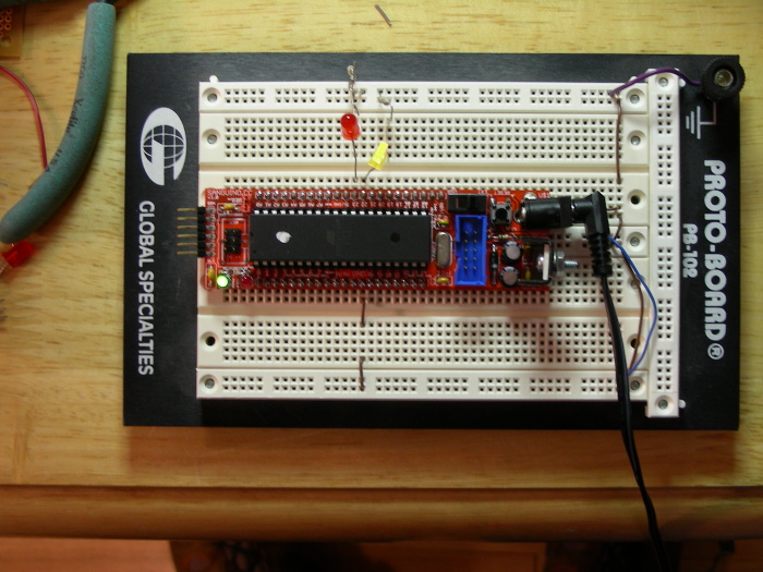
I've been pretty timid with the Sanguino haven't I? I better get serious and use all those pins that are now at my disposal. I still want to feel I did a good enough soldering job that I can control each pin, so I started plugging in LED's and resistors until I had a small forest of them on both sides of the Sanguino. Then I opened one of the sketches provided by the Sanguino 1.1 software, in the directory testers/lite_brite/lite_brite.pde, and compiled it. I uploaded it to the board and it started working my LED's nicely. This photo shows the results. Now I know that each of my available i/o pins is working. This was a good exercise because I am getting more experienced with the device, wire and LEDs.

At this time, I have not carefully investigated all the code that is in the Sanguino software "testers" directory for Sanguino software releases 1.1 through 1.3. There are a few more sketches there to play with and learn from.

If you have comments my email address is given below, slightly modified to confuse spammers. You should be able to figure out how to reconstruct the address.

Robert L. Cochran ( cochranb a tt speakeasy.net )

RBFK Dorkboard RBBB Freeduino iDuino BBB Sanguino