- This web page was last updated on
Wed, 2014 Mar 26 @ 1459 hours
- Questions about this page?
Contact us by email.
|
Totally Open Arduino-Compatible Hardware Development
|
|
|
Wulfden Freeduino with Innovations ID-12 RFID Reader
Simple straight forward setup, see table below and pictures above.
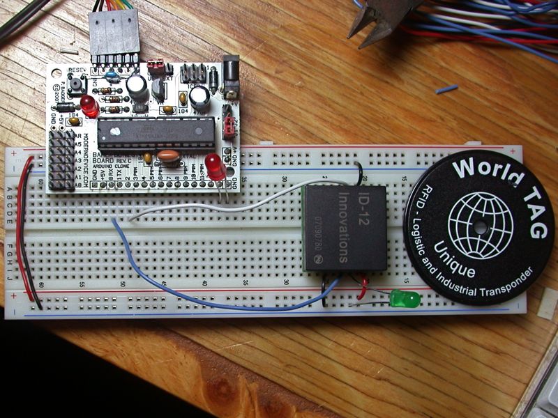
- (top left pic) Innovations ID-12 RFID Sensor from
Sparkfun
on Freeduino board powered and programmed by FTDI USB cable.
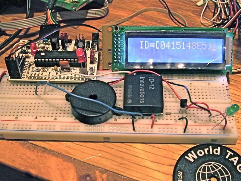
- (top right pic) ID-12 RFID on a BBB, this time with a piezo sounder in parallel with the LED and the display is to
a Wulfden K107 Serial LCD display controller. (download the associated
sourcecode here
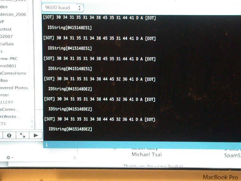
- (bottom right pic)Screenshot from Arduino IDE Serial Monitor showing output of simple demo program (download the associated
sourcecode here)
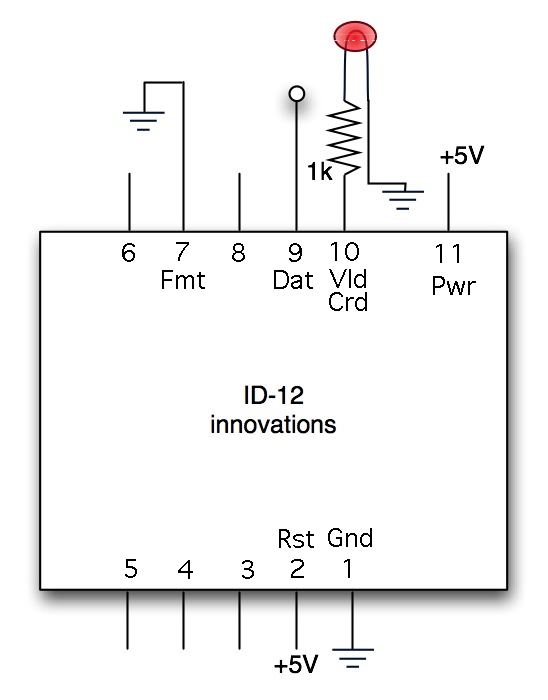
- (bottom left pic) Generalized schematic of the ID-12 - see notes below
Please take note!
- LEDs shown in pix have internal series limiting resistors. Failure to
use series limiting resistors will likely burn out the pin connected to!
- Pin 2, Reset, on the ID-12 is shown as being pulled to +5 in the schematic
to the right. This will keep the reset inoperative. My program runs it to
digital pin 2 where it is toggled after each valid read.
- If you get the ID-12 from Sparkfun, be sure to get the $0.95
breakout board
that they offer. It adapts the 2 mm pin spacing to a more standard and useable .100" spacing.
- With the Serial Data Out from pin 9 of the ID-12 connected to the Digital 0 pin
of the BBB, you will often get an error from the Arduino IDE when it tries to download a
new sketch. So when debugging code pull the wire from the breadboard in front of Digital 0,
do your download, then reinsert the wire to Digital 0.
Screen shot aboveof RFID strings read by the reader and Freeduino board. First
line shows the bytes in Hexadecimal a followed by the Text display of the 10 hex digit RFID
This is code posted to the net by Alexander Reeder in Nov 2007. He does resets of the ID-12 every few
seconds. I found this code to be workable but unstable. I altered the code to do a reset after each read of
a valid chip and found it to be quite stable. My copy of the source code is here.
This is just simple demo code to read and disply the ID in the Arduino IDE Serial Monitor window
I took my code and modified it to use the Arduino Software Serial library instead of the hardware UART.
So far this has not been successful. The read is too erratic.
A second project, building upon the first. See the fourth picture down to the right.
Display to a serial LCD display using a software serial
driver and implementing a piezo sounder to add audible indication to card recognition.
Pin 10 of the ID-12 is an output indicating an RFID chip has been read and valid checksum received.
Rather than simply asserting the pin, Inoovations sends a 3.1 KHz puls train of about 300 ms duration. Ifn
the first project, above, with just a single LED attached, this signal acts as a 50% duty cycle PWM. In this
project, the LED anode and the positive lead ofa Radio Shack piezo unit (p/n 273-073) are ti to +5 volts and
the LED cathode and negative lea of the piezo area attached to the collector of an NPN transistor (2N3904).
Its emitter grounded, the transistor's base is connected to the ID-12 pin 10 through a 1 Kohm resistor.
Thus, using the ID-12's built in capabilty we get both viusal and audible verification that the card was read.
One of the unjutly kept secrets of Arduino is that Analog 0 through Analog 5 can also be addressed
as Digital 14 through Digital 19. One of the pleasures of the BBB is the 3 pin (Gnd, +5, Signal) connectors for each
Analog input. By designating Analog 0 as Digital 14 I can easily attach a serial LCD display.
| Innovations ID-12 RFID Reader |
| Pin Name |
Pin Number |
Attached to |
| Ground |
1 |
Ground |
| Reset |
2 |
+5v pullup or
to digital pin 2 on BBB |
| n/a |
3 |
no connection |
| n/a |
4 |
no connection |
| n/a |
5 |
no connection |
| n/a |
6 |
no connection |
| Data Format |
7 |
Ground for 9600bd serial |
| n/a |
8 |
no connection |
| Data Out |
9 |
TTL TRUe serial data out
to digital pin 0 (RX) on BBB |
| Valid Card |
10 |
LED with series resistor
3.1 KHz TTL signal |
| Power (+Vcc) |
11 |
+5 VDC |
|
/*
* RFID Loop
* by Alexander Reeder, Nov 16, 2007
* Modified by Brian Riley  January 2008
*/
#define RESETLEDPin  13
#define RESETPIN     2

char val = 0;


void setup() {
    Serial.begin(9600); // connect to the serial port
    pinMode(RESETPIN, OUTPUT);    // sets the digital pin as output
    pinMode(RESETLEDPin, OUTPUT);    // sets the digital pin as output

}

void loop () {

    char IDstring[13];
    int  i;
    digitalWrite(RESETLEDPin, LOW);  // Shut off LED
    digitalWrite(RESETPIN, HIGH);    // pull up Reset line


    if (Serial.available() > 0 ) {
      if ( (val = Serial.read()) == 02 ) {    // look for Start Of Text marker
        Serial.print("[SOT] ");
                                              // reda until you get End Of Text
        for ( i = 0; (val = Serial.read()) != 03 ; i++) {
          Serial.print(val, HEX);
          Serial.print(" ");
          IDstring[i] = val;
        }
        Serial.println("[EOT]");
        Serial.println();
        Serial.print("  IDString[");
        IDstring[10] = 0x00;        // tie off IDstring at the CR-LF
        Serial.print(IDstring);
        Serial.println("] ");
        Serial.println();
        resetID12();                // reset after a valid read
      }
    }

}

void resetID12()
{
        digitalWrite(RESETLEDPin, HIGH);   // show reset by lighting LED
        digitalWrite(RESETPIN, LOW);       // pull reset down
        delay(100);

}
|
#include <SWSerialLCDPHA.h>

/*
* RFID Loop w/LCD Display and Piezo Sounder
* by Alexander Reeder, Nov 16, 2007
* Modified by Brian Riley  January 27, 2008
* Modified for Display and audible
*   Brian Riley  January 28, 2008
*/

#define  LCDpin      14
#define RESETLEDPin  13
#define RESETPIN     2
#define MISSES       5000

SWSerialLCDPHA mySerial =  SWSerialLCDPHA(LCDpin);


char val = 0;
int  misscount  = MISSES;

void setup() {

  pinMode(LCDpin, OUTPUT);  // define pin modes for tx pin
  Serial.begin(9600);       // initialize UART
  mySerial.begin(19200);   // set the data rate for the SoftwareSerial port
  mySerial.clearscr();     // gets the SW Serial pump flowing
  mySerial.clearscr();     // cleans screen after whatever goop comes from startup
  mySerial.setgeo(216);    // set chip geometry for a 2x16 display
  mySerial.setintensity(0x80);  // set backlight at mx intensity

  pinMode(RESETPIN, OUTPUT);       // sets the digital pin as output
  pinMode(RESETLEDPin, OUTPUT);    // sets the digital pin as output
  misscount  = 0;

}

void loop () {

    char IDstring[13];
    int  i;

    digitalWrite(RESETLEDPin, LOW);  // Shut off LED
    digitalWrite(RESETPIN, HIGH);    // pull up Reset line

    if (Serial.available() > 0 ) {
      if ( (val = Serial.read()) == 02 ) {      // look for Start Of Text marker
                                                // read until you get End Of Text
        for ( i = 0; (val = Serial.read()) != 03 ; i++) {
          IDstring[i] = val;
          Serial.print(val, HEX);
          Serial.print(" ");
        }
        Serial.println();
        IDstring[10] = 0x00;        // tie off IDstring at the CR-LF
        mySerial.print("?f ID=[");
        mySerial.print(IDstring);
        mySerial.print("]");
        resetID12();                // reset after a valid read
        misscount = MISSES;
      }
    } else {   // basically this code lets you see the ID for about 5 seconds then
               // replaces ID display with "waiting," 5000 1 ms loops, so if a new
               // ID card is presented it chnages immediately to new ID display.
       if (misscount-- == 0) {
          mySerial.print("?f ... waiting ...");
       }
       delay(1);
    }

}

void resetID12()
{
        digitalWrite(RESETLEDPin, HIGH);   // show reset by lighting LED
        digitalWrite(RESETPIN, LOW);       // pull reset down
        delay(100);                        // hold reset for 100 ms

}
|
|
|
|
|