Towers of Hanoi solved by robot arm connected via PRC4PR
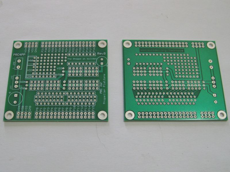
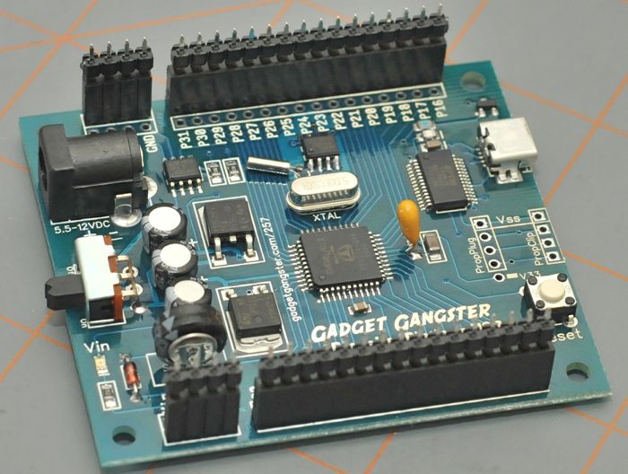
The PRC4PP is a Gadget Gangster
Platform compatible shield designed to make attaching servos and sensors a simple matter. P0-P23
have provision for standard 3 pin servo/lcd/sensor connectors (Gnd, V+, Signal). There's a small
prototyping area adjacent to P24-P31. The features are
Compatible with Gadget GangsterPropeller Platform, Propeller Platform - SD, and Pixter X Platform,
(Picaxe 40x2) Modules.
The lower 24 pins (P0-P23) are divided into three sections Bank0 (P0-P7), Bank1 (P8-P15),
and Bank2 (P16-P23)
Bank0 can be powered by The Platform Vin, or separate external Vin, or regulated 5 volts from
the Platform
Bank1 can be attached to and powered by whatever selection is made for Bank0, or whatever selection
is made for Bank2
Leaving out the headers/jumpers and hard wiring using the jumper holes any voltage can
be applied to any bank
Bank3 can be powered by either regulated 5 volts or 3.3 volts from the Platform
Alternatively the 3 pin jumpers and switch can left out and the configurations can
be hard wired with 18 gauge solid wire
If the newer Propeller Platform SD is used, P0-P3 in Bank0 will be unavailable for use
as it is taken up by the uSD card reader
Bank0 and Bank1 are laid out for a simple RC network in the signal line to minimize noise
being fed back into the Propeller by the servos.
The servo connectors are in groups of four separated by an extra gap between groups. Earlier
experience has shown that when 5 or more of the Molex connectors are stacked side by side they
start to crowd and are near impossible to securely connected
PRC4PP (Basic)
Contains the PCB, the terminal block, the switch, 3 3-pin headers, 3 shunts and the
Platform connectors (2 4-pin headers and 2 16-pin headers) and a 220 uF electrolytic capacitor.
Basic
$14 + $2
PRC4PP (Full)
Contains the full contents of the PRC4PP(Basic) kit. In addition
it contains 16 each of 1K, 100, and 220 ohm resistors (48 total), 16 0.01 uF monolithic
capacitors, and 12 2x3 pin headers (servo connectors).
Start by planning what you want to do. The first consideration is which Propeller
Platform ... the original Propeller Platform or the new SD model. If the latter the uSD uses P0-P3
so that has to be counted out of the planning. Next, how many servo's. If you have more than two
servos current capacity is an issue. the PRC4PPpower traces are doubled up and extra heavy, but pcb
mount switches don't have much capacity. You may want to use 16 or 18 gage wire in place of the
switch.
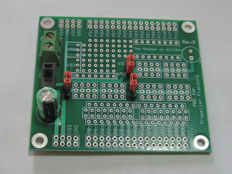
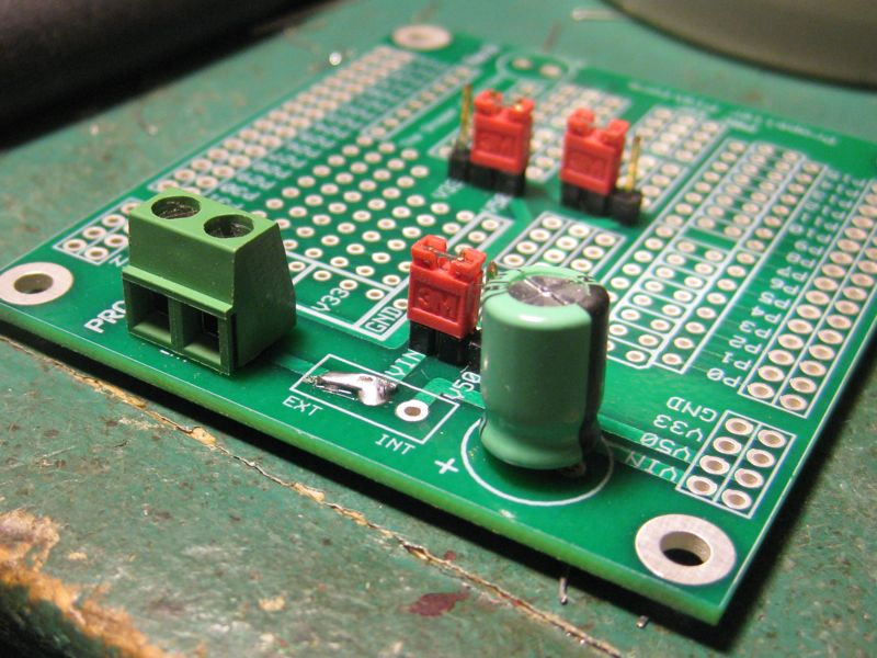
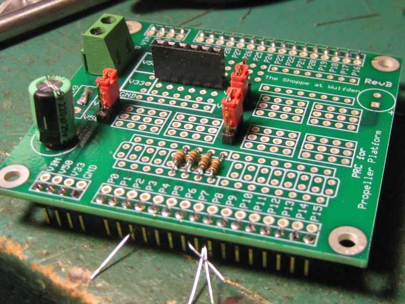
Place in the terminal block, switch (if used), and large capacitor and solder in place.
Trim the bottom of the negative terminal on the block or it will foul on the top of the Platform power
connector. As you look at this picture the upper 3-pin jumper (Bank2) and the left-most 3-pin
jumper (Bank0) ... these two pin headers will need a little extra persuasion to insert into
their holes. They will go in.
A PRC4PP with the switch replaced by 18 ga wire formed in a
"U" and inserted from the bottom of the board and folded over to double
it up, and then soldered.
Now we will place in the platform connectors. (2 4-pin and
2 16-pin headers) take a Propeller Platform or Platform SD board and insert the
4 and 16 pin headers into the appropriate sockets. Snug them down, then place
the PRC4PP pcb onto them and solder the four corner pins. Check all is
aligned then solder the remaining 36 pins. Doing it this way assures alignment.
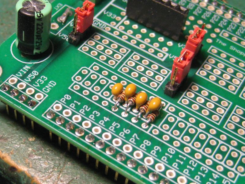
Now we put in the RC filter circuits in the servo signal lines.
This board is ultimately going to be used on a Platform SD module so we skip over
P0-P3. Place resistors in first, solder and clip leads. Then add the caps, solder
and clip.
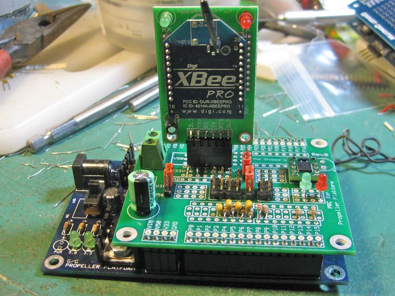
This is a nearly done project. It is the robot platform for the
PCMPM Chapter 5 Project. It contains connections for 3 servo's (I put one extra in),
a Parallax Ping))), ultrasonic range finder, two LEDs, and HM55 compass and an
XBee radio (mounted up in the small prototyping area).
Looking for more? Breadboards, power supplies,
sensors, RTCs, memory, audio boards, etc. Check our Accessories page.