The Propeller Platform is a Parallax Propeller based cpu module first
presented by Jon Williams in his "Nuts and Volts"Stamp Activities column in the
May 2009 issue. It was adopted by Nick, The Gadget Gangster, and later for a while by Parallax itself.
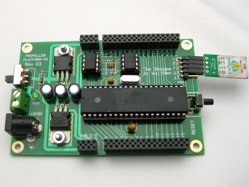
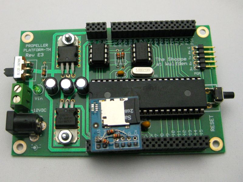
The Propeller Platform Through Hole Kit is Wulfden's DIY entry in the
Propeller Platform world. It offers the following enhancements over the original design at no increase in cost:
beefed up power traces to go with the beefed up voltage regulators
side mounted reset switch for easy access
two AT24C1024B Megabit EEPROMs, 256 KBytes total, instead of 24LC512s giving only 128 KBytes total
got rid of the extraneous 3.3v and +5v LEDs … left only the Vin LED as power indication.
power connector and terminal block can both be mounted
supply double row socket headers
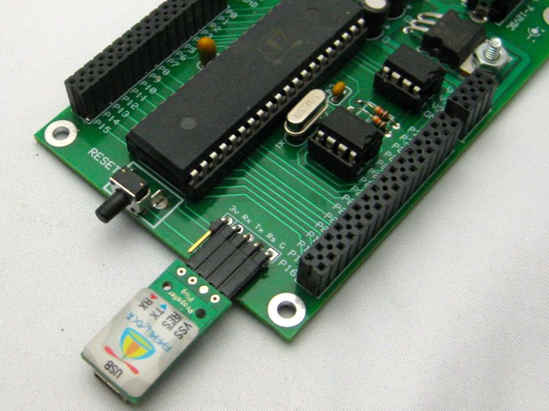
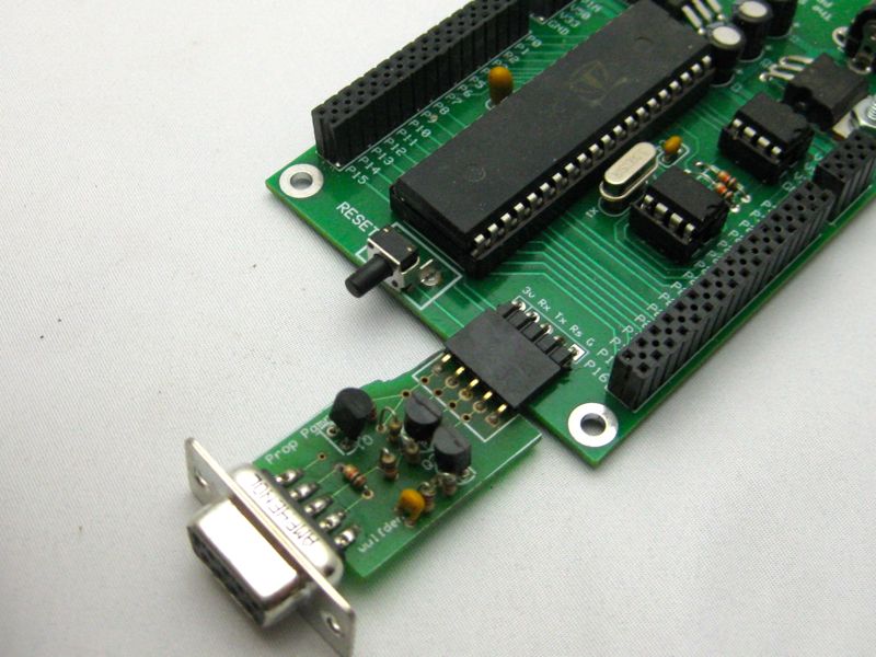
5 pin programming connector accepts, in addition to Prop Plug, Wulfden P1 and Bill Hennings
Ser Plug
You are going to need to download either the Parallax Propeller Tool or the SimpleIDE cross
platform (Windows, Mac, and linux) propeller tool suite from
Parallax Propeller software page.
Propeller Platform
Complete kit with PCB, Propeller chip, EEPROMs, Platform connectors, power circuits, etc
$37 + $3
Propeller Platform with Prop Plug
Complete kit as above, includes Parallax Propeller Plug, a USB to TTL serial
converter, optimized for programming the Propeller chip, also includes retractable USB cable.
$51 + $3
6.25 MHz Crystal for 100 MHz operation
This item can only be ordered with a kit order.
$2
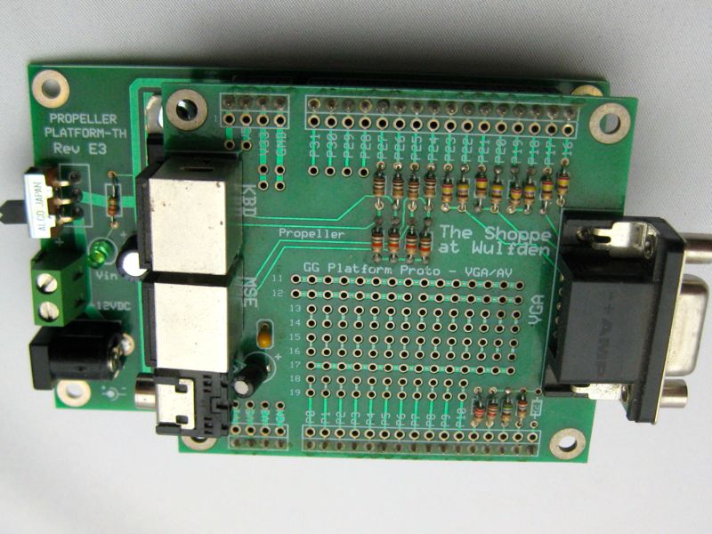
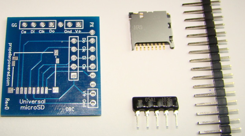
Universal Micro SD Adapter - pin headers can be assembled to match the original Gadget Gangster
layout or the slightly different Parallax layout. CS line 10K pullup easily disabled for use with Tachyon Forth.
Nick, at Gadget Gangster, has made a great video on How-To
assemble the Propeller Platform. I highly recommmend you spend the 10 minutes or so to load and view this video.
Having now built five of these board over a fairly short interval, I have few suggested changes to
the process that I have found makes it easier. They are below ... sorry, Cecil B. DeMille I am not ... still pix and text!
The comments below may seem lacking in detail if you do not view the video first
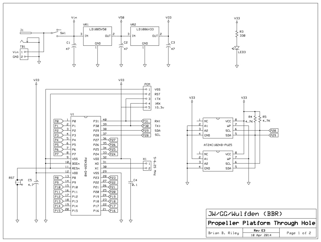
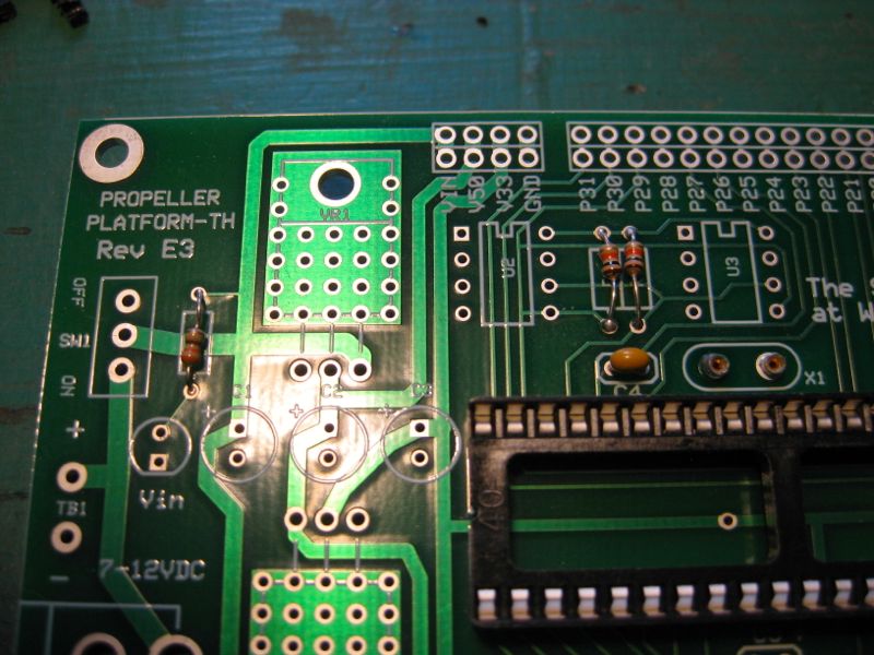
the 4.7 uF Tantalum will be at C5 and the 0.1 uF will be at C4
U2 and U3 will both be Atmel AT24C1024B (128 KBytes each)
zr3 may be a 330 to 1K ohm resistor
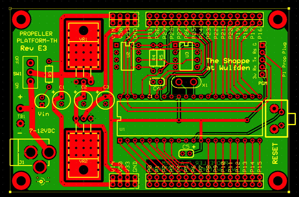
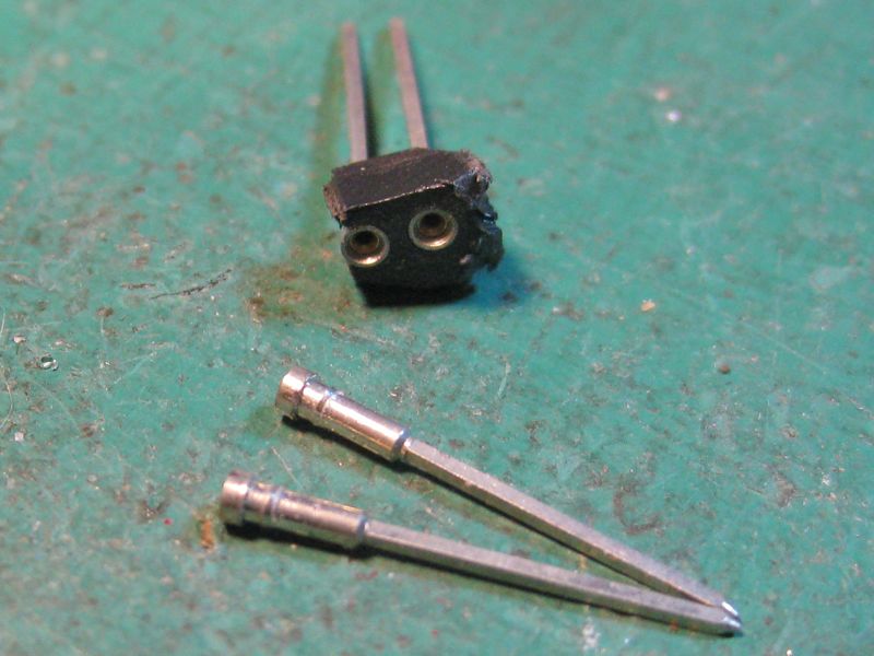
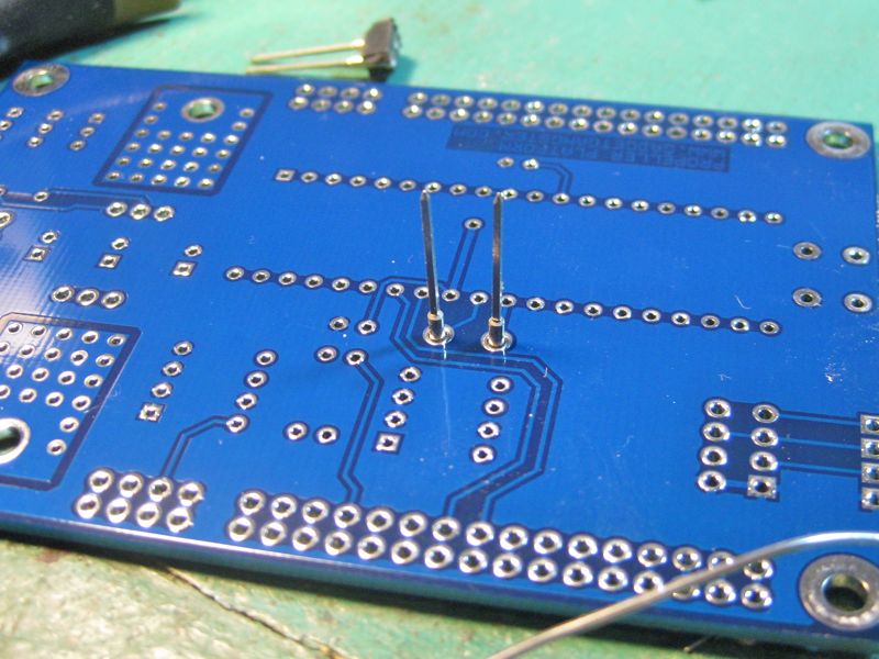
The first item installed should be the crystal socket. Break
out and clean the machine pin sockets from the plastic, then insert them through the pcb
and turn it upside down on a flat firm surface. Align them straight up and solder.
There are three 1/8 watt resistors, labeled, Left to Right, R3 through R5.
R3 - 1 Kohm (brown-black-red) - Vin LED
R4 - 4.7 Kohm (yellow-violet-red) - I2C pullup
R5 - 4.7 Kohm (yellow-violet-red) - I2C pullup
Note - The usual value for R4/R5 is 10K. While trying to push the I2C speed to 400K and 1 Meg,
we found that we observed more reliable performance with a stronger pullup (4.7K)
Now is the best time to insert and solder the small 0.1 uF monolithic cap
(marked "104"),
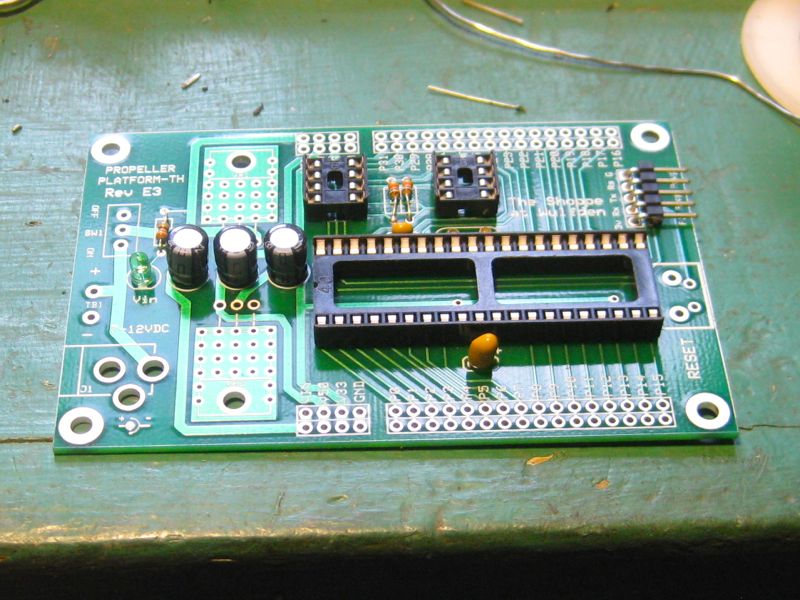
before you place the two 8 pin and one 40 pin DIP sockets. The sockets supplied are 3M dual wipe
sockets that have a kink in the legs so that they stay in the holes when you turn the
PCB over to solder. Now also would be a good time to insert and solder the 5 pin right angle
programming header(holes labeled "PGM")..
Let's get the rest of the capacitors. The 4.7 uF Tantalum is polarized.
When the writing on the side is facing you. The positive leg is to the right and the negative
leg is to the left. The negative goes to the ground hole which is to the left. The three 47 uF
electrolytcs are clearly marked, match up to the plus sign on the silkscreen. Insert the green
LED as shown. Remember on the electrolytics and the LEDs the short wire lead goes to negative.
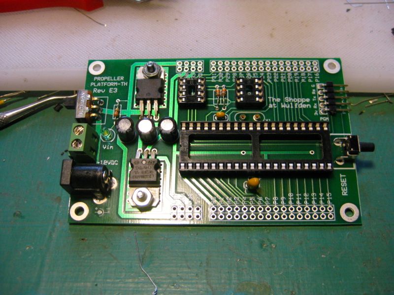
Let's do the hardware. Insert, bend the leads a little and solder the reset button.
Now decide whether to use the terminal block or the 2.1mm coaxial power connector or both. Then insert and
solder. Now, the switch. and a big decision. PCB switches of this size are rated at only 250 ma. The
regulators here are good for several times that. The traces have been beefed up. I have run over a half
amp for an hour through the switches, the official rating not
withstanding. You may want to consider leaving out the switch and using an 18 ga jumper in its place
and putting a heavier switch in the power line.
Finally put on the voltage regulators, 5V on the top and 3.3V on the bottom. Align and
bend the legs, then take some thermal heat sink compound (Radio Shack p/n 276-1372) and bolt them on
bringing the screw up from the bottom. Once they are all aligned solder and clip the leads.
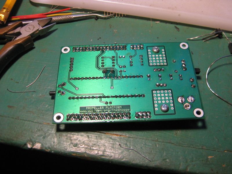
Insert the double row headers and carefully flip the board over and solder one pin
at each end. Check that header is flush to PCB reheat and reseat as needed. Solder the rest.
Looking for more? Breadboards, power supplies,
sensors, RTCs, memory, audio boards, etc. Check our Accessories page.