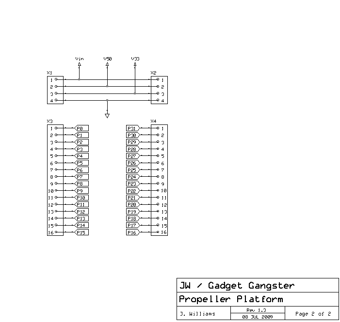
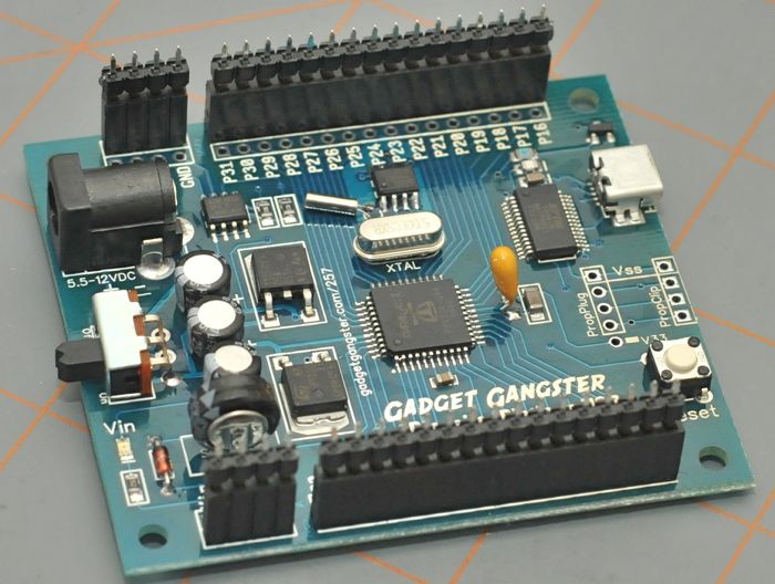
GG Platform
VGA-AV
PCB only |
Professionally fabricated double sided PCB, with plated through holes, green solder mask, and white silkscreening
|
qty = 1
$11 + $2
|
qty = 3
$30 + $3
|
GG Platform
VGA-AV
Complete Kit |
Complete kit with PCB, resistors, capacitors, VGA , 2 PS2, A/V and
male platform connectors
|
qty = 1
$20 + $3
|
qty = 3
$55 + $6
|
| All done ordering? Be sure to
check out shipping surcharges
|
| |
|
|
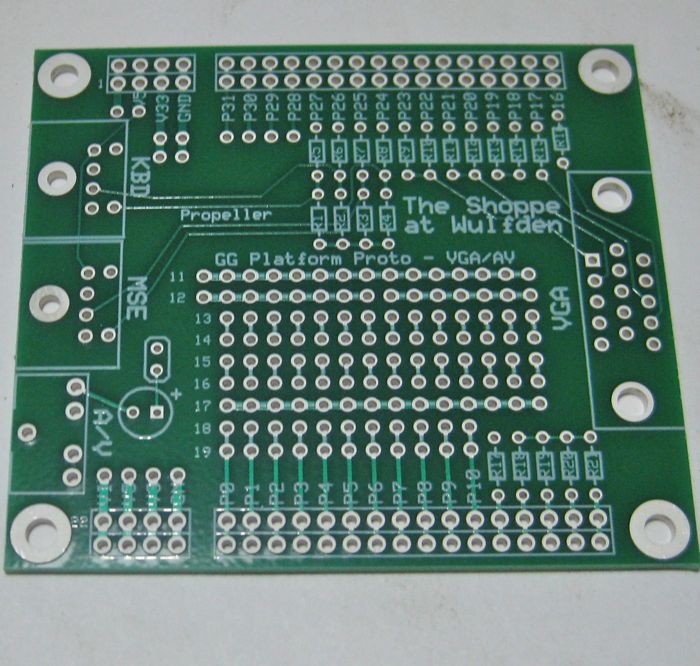
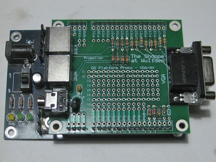
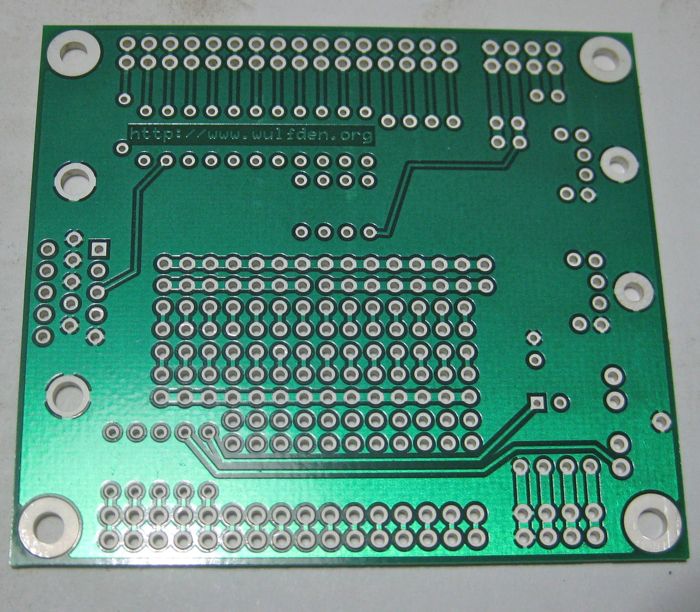
GG Platform VGA-A/V Assembly Instructions and Tips
|
|
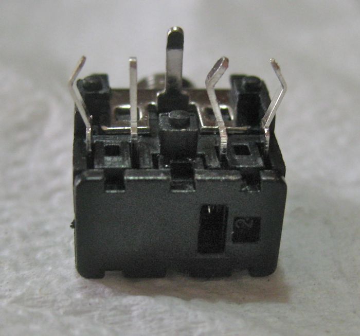
This is the A/V connector. It is a standard 3.5 mm stereo
phone jack. As you look at it, left to right, pins 5, 4, 1 (rear), 3, and 2. Pins
4 and 3 are not used but get soldered for mechanical strength. Pins 5, 3, and 2
have bent pins. Before inserting use a pair of needle nose pliers to
straighten the bends
|
|
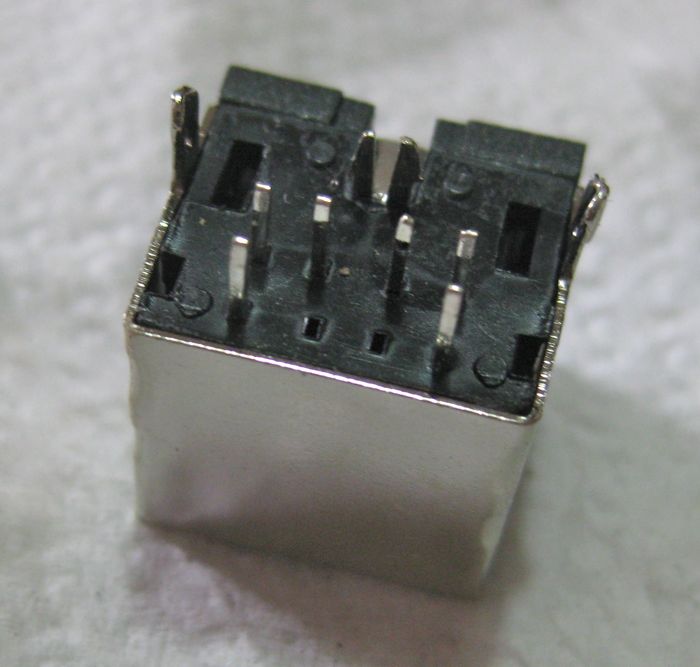
The PS2 Mouse and Keyboard connectors. There are two. Depending on which
lot of parts you get there may or may not be the two extra grounding lugs to the shell
shown in this picture. These two extra will have to be carefully cut off. You have
six fragile pins in a "C" pattern, if one is a little crooked they won't go
in. Line up the row of 4 and then wiggle and jiggle until the others drop in. Don't
force it ... have patience. It will go in!
|
|
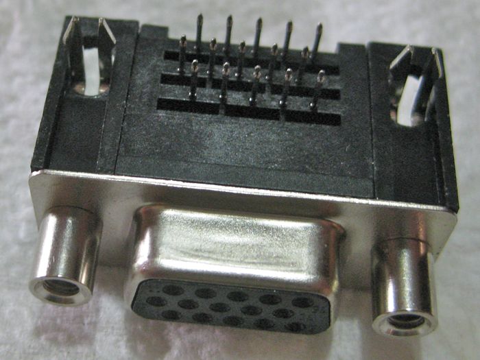
The HD15 VGA connector. If you were driven mildly batty by the PS2
connectors, hang on to your hat! The HD15 has three rows of 5 pins each, offset from
each other. The trick is to get the front or back 5 lined up and wiggle and
jiggle the rest into line. The patience of a saint, while not required, is helpful.
Its a matter of getting each group of 5 aligned for its row then placing one set of
5 in its holes and then wiggle/jiggle the other rows into place. Between an earlier
product, the prototypes and these production boards I have done this two dozen times:
fastest time two minutes, slowest time ten minutes. The thing is that the end comes
fast, one second you are wondering if it will ever go in, the next second
-pop- its in!
|
|
With all the connectors in place solder every pin and ground lug to the PCB
Inventory the bag with all of the discrete parts. With parts this size its easy
to make mistakes and packing them is a mind-numbing task. When in doubt we put extra in to make sure
you have enough to do the job. If the parts list calls for 4 and you find 5, its a bonus, BUT, do not
go nuts looking for where the extra goes. On the off chance you come up short
Contact us and we will send it out ASAP.
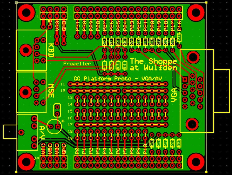
Using the parts list below and board layout to the right as a guide, we will
place, the resistors and capacitors into their holes and solder. (I suggest 4 at a time; place,
bend leads over, check value one more time, solder, the clip excess leads.)
|
|
GG Platform VGA-AV Parts List
|
| Component |
Value |
Mouser p/n |
Purpose |
| R1, R2, R3, R4 |
10 Kohm, 1/8 watt (brown-black-orange) |
299-10K-RC |
PS2 pull ups |
| R5, R6, R7, R8 |
100 ohm, 1/8 watt (brown-black-brown) |
299-100-RC |
PS2 series limit |
| R9, R11, R13, R15, R16 |
240 ohm, 1/8 watt (red-yellow-brown) |
299-240-RC |
VGA DAC |
| R10, R12, R14 |
470 ohm, 1/8 watt (yellow-violet-brown) |
299-470-RC |
VGA DAC |
| R17 |
330 ohm, 1/8 watt (orange-orange-brown) |
299-330-RC |
sound series limit |
| R18 |
1.1K ohm, 1/8 watt (brown-brown-red) |
299-1.1K-RC |
TV DAC |
| R19, R21 (optional) |
560 ohm, 1/8 watt (green-blue-brown) |
299-560-RC |
TV DAC |
| R20 |
270 ohm, 1/8 watt (red-violet-brown) |
299-270-RC |
TV DAC |
| C1 |
0.1 uF/50v monolithic ("104") |
80-C315C104M5U |
sound filter |
| C2 |
10 uF/25v electrolytic |
P807-ND (DigiKey) |
sound dc blocking |
| VGA |
HD15 pcb mount |
571-1734530-3 |
VGA connector |
| KBD, MSE |
two (2) Mini-DIN 6 female PCB mount |
161-2306 |
PS2 connectors |
| A/V |
3.5mm stereo phone jack |
161-MJ2735-5-E |
audio visual connector |
| |
(2) 1x4, (2) 1x16 male headers |
517-6111TG |
platform connectors |
|
|
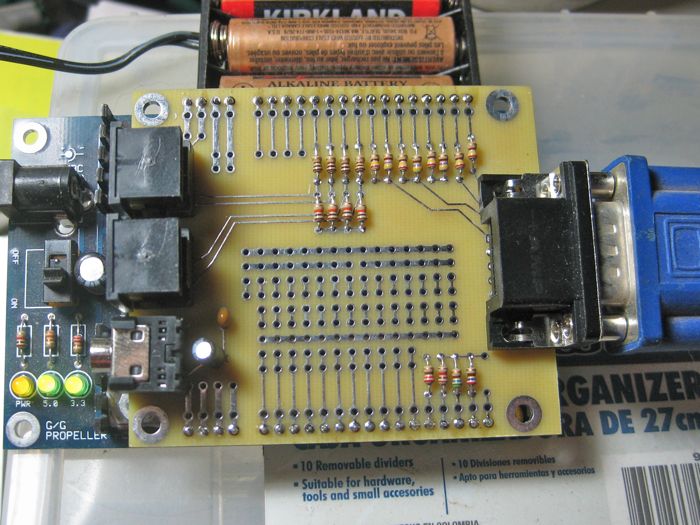
Now we put the finishing touches on by adding the platform
connectors if you have a PP or PPSD board already assembled, the easiest way to
get the pins aligned is to insert the 1x4 and 1x16 males pins in the appropriate
socket headers on the processor board, then place the VGA-A/V board onto the
pins and solder. If you don't have a processor board handy, I suggest that
you use a breadboard
|
| Looking for more? Breadboards, power supplies,
sensors, RTCs, memory, audio boards, etc. Check our Accessories page. |
|