PPLA Assembly Instructions and Tips
|
|
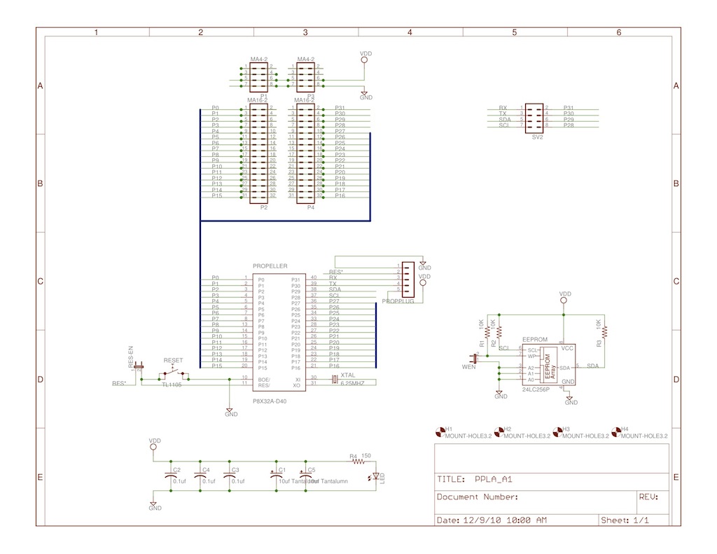
There are several minor variations from the schematic.
- C1 and C5 will be 4.7 uF Tantalum
- the EEPROM will be a 24LC512 (64 KBytes)
- R4 may be anywhere from 150 to 330 ohms
|
|
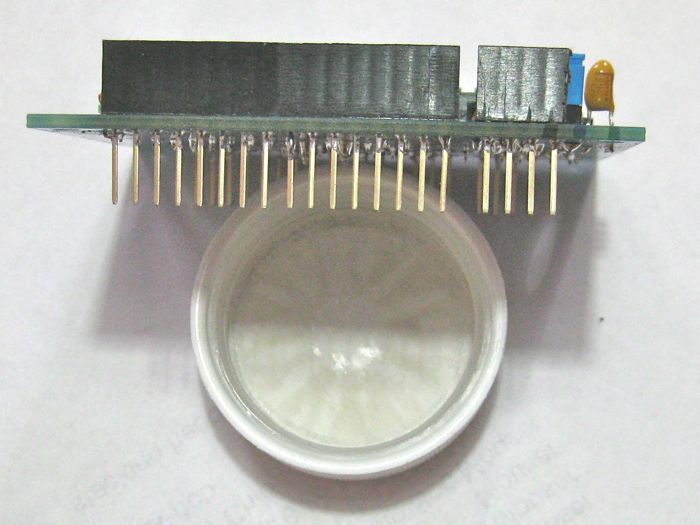
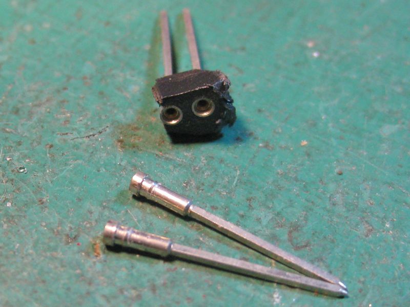
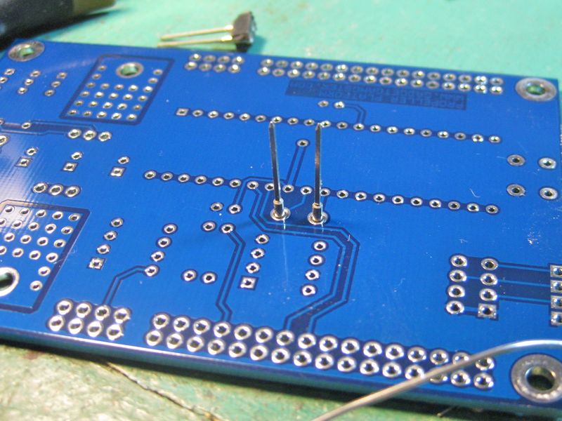
The first item installed should be the crystal socket. Break
out and clean the machine pin sockets from the plastic, then insert them through the pcb
and turn it upside down on a flat firm surface. Align them straight up and solder and clip.
|
|
|
|
Now is the best time to insert and solder the 5 pin right angle
programming header. Now also would be a good time to insert and solder the small 0.1
uF monolithic caps (marked "104"), at C2, C3, and C4. Then the 40 pin DIP
socket. The socket is 3M dual wipe socket that has a kink in the legs so that
it stays in the holes when you turn the PCB over to solder. The 8 pin DIP socket
is different. It is a machine pin socket. It has no kinks in the legs to hold it
in place. You may want to put a piece of cardboard to hold it up while getting solder
onto at least one leg.
|
|
|
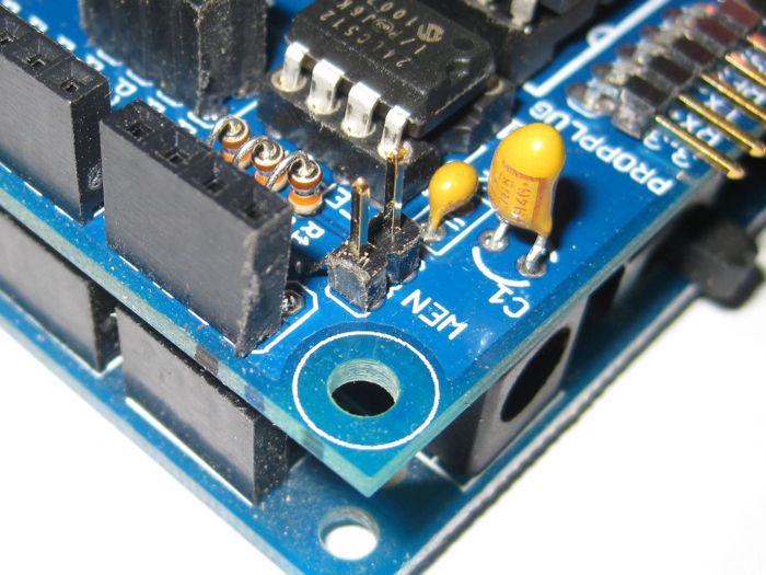
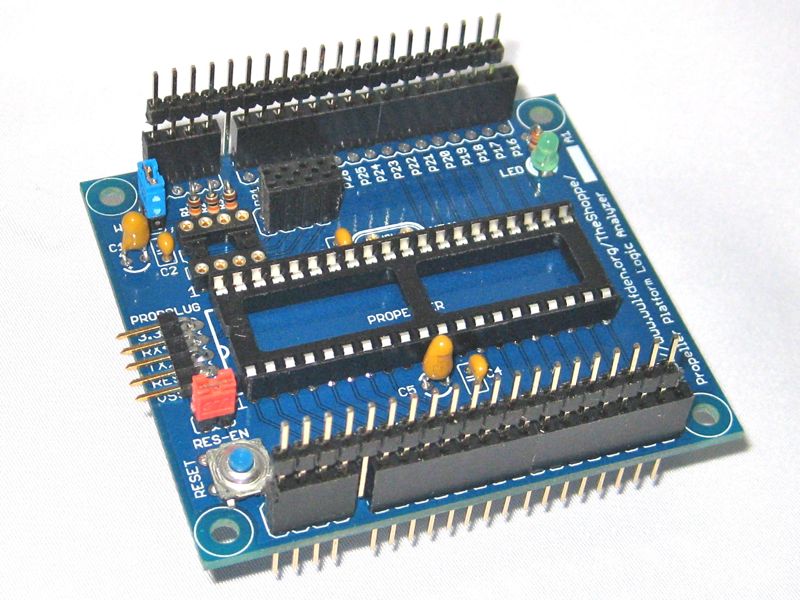
There are for 1/8 watt resistors, labeled, Left to Right, R1 through R4. They
are installed upright with top lead bent over and down in a "U"
- R1,R2,R3 - 10 Kohm (brown-black-orange) - EEPROM pullups
- R4 - 150-330 ohms - 3.3V LED
Let's get the rest of the capacitors. The two 4.7 uF Tantalum capacitors,
C1 and C5 are polarized. When the writing on the side is facing you. (see it in picture of
resistors). The positive leg is to the right and the negative leg is to the left. The
negative goes to the ground hole which is to the left.
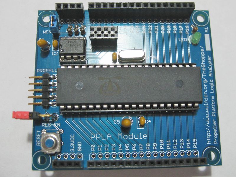
Now finish up the small components
- insert green 3mm LED. short leg away from resistor
- insert and solder one 2 pin straight male header for EEPROM Write-Enable ("WEN")
- insert and solder one 2 pin right angle male header for Reset-Enable ("RES-EN")
- insert and solder 2x4 female header
- insert and solder reset switch, pins qmay need to be spread a bit
- DO NOT INSERT CHIPS or CRYSTAL YET
|
|
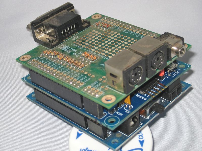
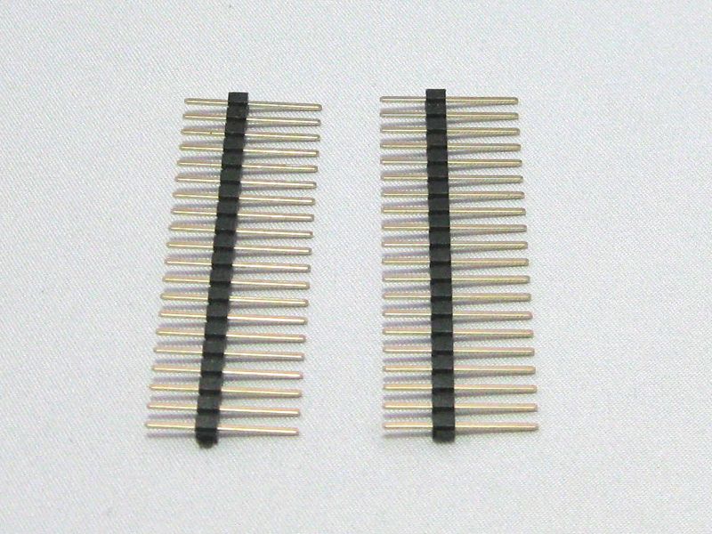
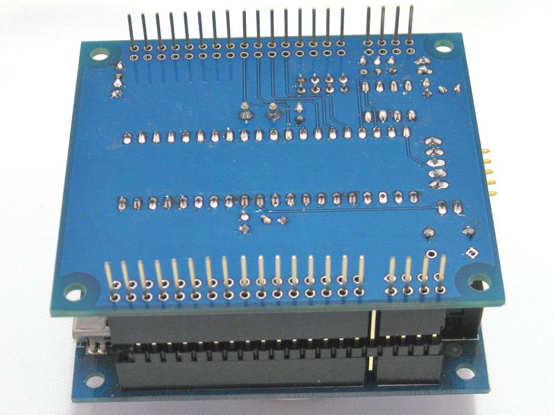
Now, the sticky one! As anyone who has worked with stacking headers can attest, they CAN
BE a royal PITA to align and solder! I am giving all Propeller Platform customers, one time only, a set of
20 pin long headers to use to align and solder.
|
|
|
|
- insert stacking headers into holes in PPLA PCB
- insert long double male headers into socket part of stacking headers. This ties
the 3 headers on each side together, making it easier to hold together for the next steps
- flip PPLA PCB over carefully and mate the second side of the double male
headers to the socket headers on a PP processor board
- you now have the pins aligned and the board upside down with gravity
holding it flush to the stacking headers
- solder the four corners to start, then finish all 40 pins
|
|
- visually inspect for unsoldered connections, shorts, and cold solder joints. Correct and
reinspect as necessary
- Using a VOM or DMM test the 3.3v buss for continuity to ground. Correct and retest as needed
- Attach PPLA to PP processor board, apply power and verify 3.3v on PPLA Module
- Remove power from units, leaving the two boards attached to each other.
- Insert chips. Having the PPLA plugged into something supports the vulnerable stacking header legs
during the forceful process of seating the 40 pin Prop chip
- Trim crystal legs and insert. Start easy, trimming too little .. you can always cut again, but
you can't add it back!
- Put Blue shunt on EEPROM Write-Enable ("WEN")
- Put Red shunt on Reset-Enable ("RES-EN")
|
|
| Looking for more? Breadboards, power supplies,
sensors, RTCs, memory, audio boards, etc. Check our Accessories page. |
|