|
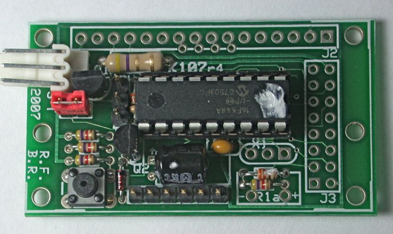
So ... this is yet another serial backpack controller board!
So ... why would you want this K107?
- Top quality double sided PCBoard (currently Rev 4), with solder mask and silkscreen. More value for your money. Costs less and does more!
- Needs only a single +5 volt dc supply @ 10 ma plus up to 200 ma for LED backlight
- For displays with LED backlights, intensity can be controlled in software to PWM hardware on board
- Can accept TTL level True serial, or RS232 level Inverted serial selectable by jumper
- Power/Signal input connector compatible with standard servo/lcd cable
- Built in self-test mode, selected by jumper
- beep and 4 software switched outputs available
- Can physically accept 1x10, 1x14, 1x16, 2x7, 2x8 display connector pin arrangements and 1x16 Flat Flex with K107RA adapter
- For DIYers, bare board available. The manual details the pin assignments so you can roll your own firmware.
- can accept 16F84, 16F628, 16F628A, 16F648, 16F648A, and 16F1827 PIC chips
- full access to 628/648/1827 USART pins
- even unused pins have plated through via's for hand wiring
- holes and traces for resonator on pins 15-16
- Main design to accept the PH Anderson line of controller chips. The K107
board will work with his LCD 106, 107, 108, 117, 117B, 117C, 117D, 118, and 118B chips.
- Wulfden currently offers with its K107 kits the LCD 117D rev of Peter Anderson's chip in 2400, 9600 and 19200 baud.
(as of Spring 2010, with the advent of the LCD117D code, the LCD118 in 2400 baud and requiring a 4 MHz resonator is no
longer necessary and no longer stocked)
- The Anderson controller firmware specifically interfaces to any character based LCD using the Hitachi HD44780 or
compatible display controller. The Anderson firmware will support 2x16, 2x20, 2x24, 2x40, 4x16 or 4x20 geometries,
under user control.
- Supports a 'large number' display mode with a four line display (4x16 or 4x20).
User defined characters, xy positioning, clear screen, home cursor, user customized splash screen, etc.
plus all of the usual range of commands.
- For ** GENERAL use ** - the K107 (Rev 4) with the Anderson 107/117/117B/117C/117D chip at 9600 baud
and interface perfectly with most processors, Basic Stamps, Freescale, PICs, etc. Most processors get easily generate 9600
baud output.
- For ** PICAXE use ** - the K107 (Rev 4) with the Anderson 117D chip
will run at 2400 baud and interface perfectly with your processor.
- For ** ARDUINO/Freeduino/Propeller use ** - the K107 (Rev 4) with the Anderson 117/117B/117C/117D chip at
19200 baud will interface perfectly with Arduino, Freeduino, and Parallax Propeller. For more details see
my Freeduino page. I have written
and Arduino Library as well as a
demo program for the K107
K107 Documentation and Manuals Complete documentation for the K107 board and kits is available only online here. In PDF format,
Acrobat Version 5 or later compatible.
- The Complete K107 Manual (through Rev 4) - 2 MB - last updated on
Sat, 2012 Jul 07 @ 1337 hours - This link will always reference the most recent
K107 manual. Which will contain reference diagrams and schematics for all prior revisions of the K107 board.
- Jumper Summary and Input Connections Sheet - 200KB - last updated on
Sun, 2008 Feb 10 @ 1833 hours - Signal input pinouts, test mode and signal level jumper settings
- Anderson Command Set Summary - last updated on
Sun, 2008 Feb 17 @ 2139 hours- An excellent one page command set cheat sheet by MyCroft.
- Complete Rev 3 Manual - 2 MB - last updated on
Sun, 2012 Jul 22 @ 1852 hours - This is a 20+ page illustrated manual, containing schematics, parts lists,
parts layouts, assembly instructions, software interfacing, etc. Manual contains information on the K107RA, and layouts and schematics for Rev 1 and
Rev 2 K107 boards
- Complete Rev 2 Manual - 4 MB - last updated on
Sun, 2008 Feb 10 @ 1842 hours - This is a 17 page illustrated manual, containing schematics, parts lists,
parts layouts, assembly instructions, software interfacing, etc.
- Rev 2 Summary Sheet - 500KB - last updated on
Sun, 2008 Feb 10 @ 1833 hours - schematic, pin assigments, parts list, parts layout
- Complete Rev 1 Manual - 4 MB - last updated on
Sun, 2008 Feb 10 @ 1834 hours - This is a 14 page illustrated manual, containing schematics, parts lists,
parts layouts, assembly instructions, software interfacing, etc.
Basic K107 Product Line
- Board Only - exactly what it says, just the K107 PCBoard
- Board and Chip - K107 PCboard and Anderson chip
- Board and Parts - the K107 PCBoard plus all the support parts EXCEPT the Anderson chip - assumes you already have one
or are planning to do a custom program to your own blank chip.
- Complete Kit - contains the K107 PCBoard, the Anderson chip, and all the parts you need to
completely populate the K107 PCB; male and female 1x16 and 2x8 pin headers which will let you connect to 1x10, 1x14,
1x16, 2x7, and 2x8 displays. The kit also incldes a 3 wire 14" servo/lcd cable with female Molex KK connectors
- Rock Bottom Kit - the complete kit (see above) without parts for RS232 input and
only one set of display connectors, your choice 1x16 or 2x8
- Ribbon Adapter - the K107RA PCBoard adapter board allows interfacing to displays that have 16 conductor 1 mm pitch Flat Flex
(FFC/FPC) connections. Kit consists of board, 1x16 pinheader, and FFC/FPC connector
- Special Display and adapter for the AMQRP PIC-EL project and also Tom Lackamp's All In One Remote can be found
here.
|